Electric bike controllers are vital, managing speed, battery, and features like lights; a pdf wiring diagram is essential for repairs, modifications, and custom builds.
Understanding the controller wiring is crucial, with diagrams detailing connections between throttle, motor, battery, and hall sensors for optimal performance and safety.
What is an E-bike Controller?
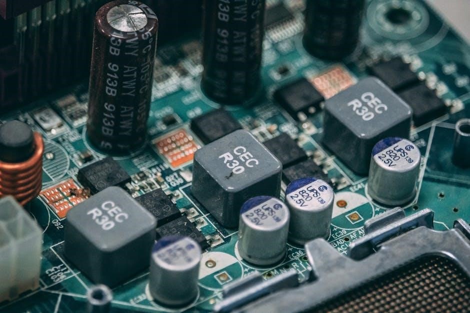
The e-bike controller functions as the central nervous system of your electric bicycle, orchestrating the flow of power and information between all critical components. Essentially, it’s a sophisticated circuit board—often housed in a metal casing—that regulates the motor’s speed, manages battery usage, and frequently integrates functionalities like lighting systems and pedal assist. A detailed electric bike controller circuit diagram pdf is invaluable for anyone seeking to understand its inner workings.
This component receives input from the throttle and/or pedal assist sensor, interpreting rider commands and translating them into signals for the motor. It also monitors crucial parameters like voltage, current, and temperature, ensuring safe and efficient operation; The controller utilizes Pulse Width Modulation (PWM) to control the power delivered to the motor, allowing for smooth acceleration and precise speed control. Accessing a pdf schematic allows for troubleshooting, repair, and even customization of the system. Understanding the diagram is key to unlocking the full potential of your e-bike.
Importance of a Controller Circuit Diagram
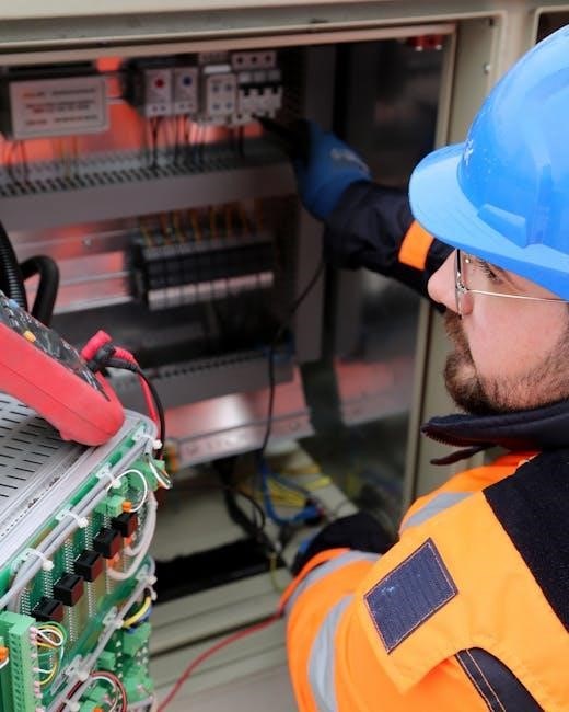
An electric bike controller circuit diagram pdf is paramount for anyone involved in e-bike maintenance, modification, or custom builds. It provides a visual roadmap of the controller’s internal connections, component placement, and signal pathways. Without it, diagnosing issues becomes significantly more challenging, often relying on guesswork rather than informed troubleshooting. The diagram details the relationships between the microcontroller, MOSFETs, hall sensors, and other vital elements.
For repairs, a schematic allows you to pinpoint faulty components quickly and efficiently. When undertaking modifications – such as increasing power output or adding new features – the diagram is essential for understanding how to safely integrate changes. Furthermore, for those building custom e-bikes, a pdf schematic is indispensable for proper wiring and configuration. Resources like Microchip application notes and Albert van Dalen’s KU63 controller documentation offer valuable insights into these diagrams, empowering users to confidently work with their e-bike systems.
Types of E-bike Controllers (BLDC vs. Hub Motor)
Electric bike controllers broadly fall into two categories: those for Brushless DC (BLDC) motors and those integrated within hub motors. Understanding this distinction is crucial when referencing an electric bike controller circuit diagram pdf. BLDC controllers, often external units, manage the motor’s speed and torque via precise commutation, relying heavily on hall sensor feedback – details clearly shown in the diagram.
Hub motor controllers, conversely, have the control circuitry built directly into the wheel hub. While the fundamental principles remain the same, the physical layout and wiring differ significantly. A pdf schematic for a hub motor controller will illustrate the integrated components and connections within the hub itself. Resources like VESC open-source projects showcase detailed diagrams for both types. Examining these diagrams reveals how each controller type manages power delivery and motor control, impacting performance and efficiency.
Core Components of an E-bike Controller Circuit
E-bike controllers utilize MCUs, MOSFETs/IGBTs, and hall sensors; a pdf circuit diagram illustrates these components and their interconnectedness for efficient motor control.
Microcontroller Unit (MCU)
The Microcontroller Unit (MCU) is the central processing unit within the e-bike controller, acting as the ‘brain’ of the system. Examining an electric bike controller circuit diagram pdf reveals the MCU’s pivotal role in interpreting signals from various sensors – throttle position, pedal assist sensors (PAS), and hall sensors – and translating them into commands for the motor.
These commands control the switching of power to the motor windings via MOSFETs or IGBTs. The MCU’s programming dictates the motor’s speed, torque, and overall performance characteristics. Microchip’s application note (AN857A) and STMicroelectronics documentation (CD00004396) detail how MCUs manage these complex processes.
Different MCUs offer varying levels of processing power and features, impacting the controller’s capabilities. Open-source projects like VESC utilize powerful MCUs for advanced control algorithms and customization. The pdf diagrams showcase the MCU’s connections to other essential components, highlighting its central position in the e-bike’s electronic architecture.
MOSFETs and IGBTs (Switching Devices)
MOSFETs (Metal-Oxide-Semiconductor Field-Effect Transistors) and IGBTs (Insulated-Gate Bipolar Transistors) are the workhorses of power delivery in an e-bike controller. An electric bike controller circuit diagram pdf clearly illustrates these components as switches, rapidly turning the motor windings on and off to create motion. They are controlled by signals from the MCU.
MOSFETs are commonly used in lower-power controllers, while IGBTs handle higher voltages and currents, often found in more powerful systems. The choice depends on the motor’s voltage and current requirements. These switching devices are crucial for Pulse Width Modulation (PWM), a technique used to regulate motor speed and torque efficiently.
Analyzing diagrams from resources like Albert van Dalen’s KU63 controller reveals how these devices are arranged in a bridge configuration. Proper heat sinking is vital for MOSFETs and IGBTs, as they generate significant heat during operation. The pdf schematics detail the necessary protection circuitry surrounding these components.
Hall Sensor Integration
Hall sensors are integral to BLDC motor control, providing crucial rotor position feedback to the e-bike controller. An electric bike controller circuit diagram pdf will depict these sensors strategically placed within the motor, generating signals that inform the MCU about the motor’s rotational state.
Typically, BLDC motors utilize three Hall sensors, each corresponding to a specific winding phase. The controller interprets the sequence of signals from these sensors to determine the correct commutation timing. Microchip’s application note (AN857A) details this process, showing how the MCU decodes Hall sensor data.
The pdf diagrams illustrate the Hall sensor wiring – often a five-wire connection providing both power and signal lines. Accurate Hall sensor integration is vital for smooth, efficient motor operation. Incorrect wiring or faulty sensors can lead to jerky movement or complete motor failure. Open-source projects like VESC emphasize precise Hall sensor calibration.
Understanding BLDC Motor Control
BLDC motor control relies on precise commutation, achieved by sequentially energizing motor windings; a pdf diagram illustrates this process, showing how the controller manages power.
Understanding commutation principles, aided by a circuit diagram, is key to optimizing e-bike performance and efficiency, ensuring smooth and reliable operation.
Commutation Principles
Commutation in BLDC motors is the process of energizing the stator windings in a specific sequence to create a rotating magnetic field, driving the rotor. Unlike brushed motors with mechanical commutation, BLDC motors utilize electronic commutation controlled by the e-bike controller.
A detailed electric bike controller circuit diagram pdf visually demonstrates this sequence. The controller, guided by hall sensor feedback, determines which windings to energize and when. This precise timing is critical for maintaining motor torque and speed. The diagram will illustrate how the MCU (Microcontroller Unit) signals the MOSFETs or IGBTs to switch power to the windings.
Effective commutation requires knowing the rotor’s position. Hall sensors, strategically placed within the motor, provide this information to the controller. The pdf diagram will show the hall sensor wiring and their relationship to the controller inputs. Proper commutation minimizes noise, maximizes efficiency, and extends motor lifespan. Incorrect commutation leads to jerky operation and potential motor damage, making understanding the diagram essential for troubleshooting.
Role of Hall Sensors in Commutation
Hall sensors are pivotal in BLDC motor control, providing crucial rotor position feedback to the e-bike controller. An electric bike controller circuit diagram pdf clearly illustrates their integration, showing how they connect to the controller’s input pins. These sensors detect changes in the magnetic field as the rotor rotates, generating signals that pinpoint the rotor’s exact location.
The controller utilizes these signals to determine the correct sequence for energizing the stator windings – the core of commutation. Without accurate hall sensor data, the controller cannot properly time the winding energization, resulting in inefficient or failed motor operation. The pdf diagram highlights the typical three-wire configuration of hall sensors, each corresponding to a specific winding phase.
Understanding the hall sensor arrangement and wiring, as depicted in the diagram, is vital for diagnosing commutation issues. A faulty hall sensor or incorrect wiring can disrupt the commutation process, leading to motor stuttering or complete failure. Proper interpretation of the diagram ensures accurate troubleshooting and repair.
Back EMF and its Significance
Back Electromotive Force (Back EMF) is a voltage generated within the motor windings as the rotor spins, opposing the applied voltage. An electric bike controller circuit diagram pdf doesn’t directly show Back EMF, but understanding its role is crucial when interpreting controller behavior. The controller leverages Back EMF for speed regulation and efficient operation.
As motor speed increases, Back EMF rises, reducing the effective current flow. The controller monitors this voltage to estimate motor speed and adjust power delivery accordingly. This feedback loop is essential for maintaining desired speed and preventing overcurrent situations. The pdf diagram illustrates the controller’s sensing inputs, which indirectly relate to Back EMF monitoring.
Analyzing Back EMF characteristics can aid in diagnosing motor or controller issues. Abnormal Back EMF readings, detectable through controller diagnostics, can indicate winding shorts, demagnetization, or mechanical problems. Recognizing its significance, alongside the wiring diagram, empowers effective troubleshooting and maintenance.

E-bike Controller Wiring Diagrams – A Deep Dive
E-bike controller wiring pdf diagrams detail throttle, PAS, display, and lighting connections; understanding these configurations is key for repairs and customizations.
Standard Wiring Configurations
E-bike controller wiring, as illustrated in typical circuit diagram pdfs, generally follows a standardized pattern. The battery connects to the controller’s main power input, providing the necessary voltage for operation. From there, power is distributed to the motor via thick gauge wires, often utilizing three-phase connections for BLDC motors.
The throttle, a crucial input device, connects to a designated port on the controller, signaling desired speed. Pedal Assist Systems (PAS) sensors also connect to the controller, providing input based on pedaling cadence. Hall sensors, integral to motor control, connect to specific pins, providing rotor position feedback.
Controllers also feature connections for displays, allowing riders to monitor speed, battery level, and other parameters; Lighting systems, including headlights and taillights, are often integrated, drawing power from the controller. A pdf wiring diagram clearly depicts these connections, ensuring correct installation and functionality. Proper wiring is paramount for safe and efficient operation.
Throttle and Pedal Assist System (PAS) Connections
Analyzing an e-bike controller circuit diagram pdf reveals specific wiring for throttle and PAS systems. Throttles typically connect via a three-wire configuration: positive voltage, ground, and signal wire. The signal wire transmits a voltage proportional to the throttle position, dictating motor speed.
PAS sensors, conversely, generate pulses as the pedals rotate. These pulses are sent to the controller, activating motor assistance. Wiring usually involves a two or three-wire connection, providing power and signal. The controller interprets these signals to deliver assistance levels based on pedaling effort.
Correctly identifying these connections within the pdf is crucial. Incorrect wiring can lead to erratic behavior or system failure. Some controllers offer adjustable PAS levels, configurable through software or dip switches. Understanding these nuances, as detailed in the diagram, ensures optimal performance and a customized riding experience.
Display and Lighting Integration
An e-bike controller circuit diagram pdf illustrates how displays and lighting systems connect. Displays, often LCD or LED, communicate with the controller via protocols like UART or CAN bus. These connections transmit data regarding speed, battery level, assistance mode, and other vital information. The pdf details pin assignments for power, ground, and data transmission.
Lighting integration typically involves separate connections for headlights, taillights, and brake lights. These are usually powered directly by the controller or through a dedicated power supply. The diagram clarifies wiring for switching and dimming functions, often controlled by the display or controller settings.
Proper integration ensures seamless operation and adherence to safety regulations. Incorrect wiring can damage components or create hazardous conditions. The pdf serves as a critical guide for correctly interfacing these systems, enabling a fully functional and informative e-bike experience.
Resources for Finding E-bike Controller PDFs
PDF diagrams are available from Microchip (AN857A), STMicroelectronics (CD00004396), open-source projects like VESC, and Albert van Dalen’s KU63 controller resources.
Microchip Application Notes (AN857A)
Microchip’s Application Note AN857A provides a comprehensive explanation of building a basic Brushless DC (BLDC) motor controller, offering valuable insights into the fundamental principles of operation. This document details the necessary components and circuitry involved in controlling a BLDC motor, which is commonly used in electric bikes.
While not specifically an e-bike controller pdf, it serves as an excellent foundation for understanding the core concepts. The application note covers topics like PWM generation, commutation logic, and the role of Hall effect sensors in determining rotor position. It illustrates a practical implementation using Microchip’s PIC microcontrollers and associated power electronics.
The schematic diagrams and explanations within AN857A are particularly helpful for those seeking to understand the inner workings of a BLDC controller circuit. It’s a valuable resource for hobbyists, students, and engineers looking to design or troubleshoot their own e-bike control systems, providing a solid base for more complex designs.
STMicroelectronics Documentation (CD00004396)
STMicroelectronics’ document CD00004396 details a three-phase inverter for motor control, offering a practical example of the power stage commonly found within an e-bike controller. Although not a complete e-bike controller pdf, it provides a detailed circuit diagram and explanation of the key components involved in driving a BLDC motor.
This documentation focuses on the gate driver circuitry and power MOSFET selection, crucial aspects of efficient and reliable motor control. It outlines the considerations for designing a robust inverter capable of handling the high currents and voltages associated with e-bike motors. The document also touches upon protection features, essential for ensuring the longevity of the controller.
While it doesn’t cover the microcontroller aspects, understanding the inverter design presented in CD00004396 is vital for anyone seeking a deeper understanding of the power electronics within an e-bike controller. It complements resources like Microchip’s AN857A, offering a more focused view of the power stage implementation.
Open-Source Projects (VESC) and Albert van Dalen’s KU63 Controller
For those seeking comprehensive e-bike controller pdf schematics and code, open-source projects like VESC (Vedder Electronic Speed Controller) are invaluable. VESC provides fully open hardware and software designs, allowing for deep customization and understanding of the controller’s inner workings. Detailed circuit diagrams, component lists, and firmware are readily available online.
Alternatively, Albert van Dalen’s KU63 controller offers a simpler, yet effective, open-source design. His website (avdweb.nl) hosts schematics and documentation for this controller, providing a good starting point for DIY builds or educational purposes. The KU63 focuses on simplicity and efficiency, making it easier to grasp the fundamental principles of e-bike control.
Both VESC and the KU63 represent excellent resources for accessing detailed pdf-based controller diagrams and gaining practical experience with e-bike controller design and implementation. They empower users to modify, repair, and build their own controllers.